





60 Cubic Meter 3-Axle LPG Gas Tank Trailer
 Nov 06, 2025|
 View:316
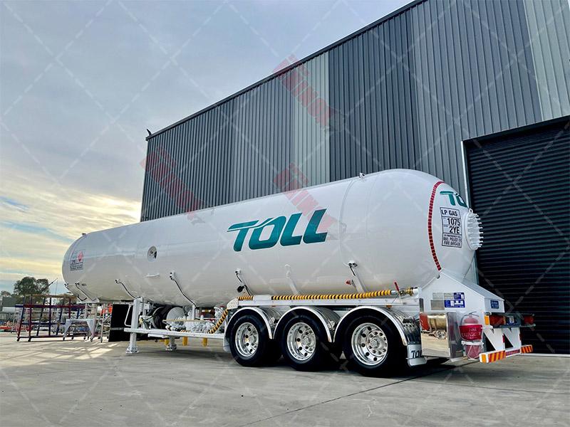
The 60 cubic meter 3-axle LPG gas tank trailer is a highly sophisticated piece of engineering designed for the safe and efficient transportation of liquefied petroleum gas (LPG). Various terrains and differing lengths of transport are within its primary scope of operation. Robust construction, coupled with more advanced forms of incorporated safety features, meet the near constant demands placed upon trailers by the energy and subsequently the logistics sectors. A capacity of 60 cubic meters represents the near perfect balance between payload efficiency and all round road maneuverability; regional distribution as well as some form of long haul is fully within its capabilities.
LPG tank trailers serve as near essential links in the current energy supply chain - propane, butane (or mixtures) being transported from point of production (including import terminals) to smaller distribution centers and end users. The three axle configuration provides superior weight distribution, stability being a key required factor, smaller trailers not achieving this to the same extent and larger multi-axle styles losing some degree of road accessibility. International standards (ASME, DOT, ADR to name a few) dictate many aspects of their safe operation.
The market for LPG transportation is and will continue to grow, cleaner energy being a primary motivator for this transition. Mid to large scale transport solutions are what the 60m³ trailer was built for; diverse infrastructure will always present certain limitations, payload (within legal weights) being the end goal. Cylindrical tank designs with semi-elliptical heads are typical, high strength steel being used and all the associated modern safety and/or monitoring systems now a near universal part of the trailer's make up.
Working Principle
The true operational principle of these trailers is simple: maintaining the liquefied state of the gas, and all that it allows in terms of both safety and transportable volume.
Pressure Management System
The tank operates as a pressurized vessel; internal pressures are generally maintained between 5-18 bar. The specific composition of the LPG and ambient temperature are factors influencing this pressure. Keeping the LPG in a liquid state is the primary purpose of this pressure - volumes are significantly reduced compared to their gaseous form (approximately 250x less). Structural integrity of the tank itself, combined with the inherently variable vapor pressure of the LPG, maintains these pressures.
Loading and Unloading Mechanisms
At terminals, loading is achieved via bottom-loading arms connected to a trailer's manifold system. Liquid enters through the designated bottom valves, equalization lines managing the associated vapor displacement. Unloading can follow either a pressure differential method (the tank 'pushing' its contents out using self-generated vapor pressure) or external pumping. More advanced models utilize some form of internal submerged pump for near instantaneous, controlled discharge.
Temperature Compensation
Fluctuating ambient temperatures during transit cause expansion and contraction of the LPG. Ullage space within the tank design (10-15% of total volume being ideal) accommodates this, safe pressure limits being the end point of compensation. Pressure relief valves are the first line of defense, venting any excess vapor; thermal safety valves provide the further, fire-related protection.
Stability and Dynamics
A three axle configuration distributes the gross vehicle weight (35-40 tons loaded being typical) evenly over all road surfaces. Robust chassis mounting and to a large extent modern suspension systems, dampen all forms of vibration and/or shock - constant small scale stress on the tank and all internal fittings must be kept to a minimum.
Key Features
Structural Integrity
High tensile strength steel (P460NL2 or equivalent) is used
Automatic welding processes
Safety Systems (as above)
Emergency shutdown systems capable of being remotely or automatically activated; leaks and certain types of accidents being the triggers
Robust impact protection guards specifically for valves and fittings
Fire-resistant insulation and/or coatings as regulated
Comprehensive overturn protection - preventing a tank from rupturing in a rollover scenario
Operational Efficiency
An advanced manifold system with quick connect couplings; faster loading/unloading being the primary goal
Internal baffles or some form of surge plate to minimize undesirable liquid movement during transit
Lightweight design, maximizing possible payload within legal weight limits
Low profile design (stability and wind resistance being key factors)
Monitoring and Control
Integrated electronic monitoring systems - pressure, temperature, fill level all being tracked
Telematics type capabilities for both real time location and more general 'conditi
on' monitoring
Automated documentation (inventory style) systems, regulatory compliance being a major focus
Remote monitoring options for the end user/fleet management
Maintenance and Serviceability
Easy access to all valves and components (inspection and/or routine maintenance)
Corrosion protection (coatings being preferred, sacrificial is a last resort)
Standardized components where possible
Designs that allow for near complete internal inspection and cleaning
Production Process
Design and Engineering Phase
The production begins with detailed engineering design. CAD/CAE software is used to optimize every aspect: structural integrity, weight distribution, near perfect compliance to all forms of regulation. Finite element analysis simulates all expected stress points, CFD models the more 'intangible' fluid related behaviors throughout the life of the tank.
Material Selection and Preparation
High quality pressure vessel steel plates are selected (chemical and mechanical properties certified). Precise cutting is achieved via computer controlled plasma or laser systems. Hot formed cylindrical sections are then rolled, end heads are hot spun or pressed.
Tank Fabrication
Longitudinal welding is performed using SAW, circumferential joins follow suit. Non-destructive testing at all stages is a part of the final product quality.
Heat Treatment
The completed tank shell undergoes stress relief heat treatment within computer-controlled furnaces. Reducing residual stresses inherent in the welding process is the primary objective; improved mechanical properties of the material are a closely related secondary benefit. Cyclic loading conditions specific to transport operations make these aspects particularly important to address.
Assembly Integration
The pressure vessel is mounted onto a heavy duty chassis, high strength steel beams being used for the fabrication of this structure. A suspension system (air-ride being the more common form, mechanical leaf springs alternatively) is installed, along with all associated braking and lighting systems. Axles are positioned to optimize some form of weight distribution - regional regulations often dictate the final acceptable levels.
Systems Installation
The manifold system, various valves and any pre-determined safety devices are installed according to precise engineering specifications. Piping is routed, accessibility and protection from physical damage being top considerations. Electrical systems (lighting, monitoring type, and/or control) follow, sealed and all round protected.
Testing and Certification
Each completed trailer goes through comprehensive testing:
Hydrostatic pressure - 1.5x design pressure at least temporarily to test structural integrity
Leak testing (sensitive methods are used for all connections/welds)
Functional testing of every possible valve or monitoring system
Road testing (braking, small to medium scale handling, suspension as previously mentioned)
Final inspection, again against all design and/or regulatory based parameters.
Finishing and Delivery
Surface preparation and painting (corrosion resistant, epoxy/PU type) occurs. Design calculations, material certifications and all test reports are compiled and delivered to the end customer or user.
Technical Parameters of Trailer / Tank Capacity
Water capacity: 60m³
Working volume: ~54m³ (to the above stated safety limits)
Overall length: 12-13.5m
Weight (tare or otherwise): ~13.5 tonnes
All of the above can and will be tailored to a range of end uses.
Payload capacity: 22,000-26,000 kg of LPG
Gross vehicle weight: Typically 35,000-40,000 kg, regional regulations influencing the exact figure
Pressure Ratings
Design pressure: Usually 17.5-18 bar
Test pressure: 26.25-27 bar (1.5 x design pressure)
Maximum working pressure: 15.75-16.2 bar (90% of design pressure)
Relief valve setting: Typically 17.5 bar
Material Specifications
Tank material: High-strength low-alloy steel such as P460NL2, P355NL2, or equivalent
Wall thickness: Varies along length, shell being the thickest part - 8 to 12 mm is common, heads thicker
Chassis material: High tensile steel (minimum yield strength 355 MPa)
Operational Parameters
Number of compartments: 1-3 separate compartments, individual manifolding preferred
Unloading rate: Near constant, pump system dependent (1000-1500 l/min is typical)
Maximum operating temperature: 50°C
Minimum design temperature: -20 to -40°C (specification based)
Regulatory Compliance
Design codes: ASME Section VIII, EN 12493, ADR/RID/TPED
Transportation regulations: ADR (Europe), DOT (USA) and all equivalent forms
Environmental standards: All current and near future emissions or 'greening' type standards are being met
The 60 cubic meter 3-axle LPG tank trailer represents a mature technology. Continuous small scale evolution is and will always be a part of its design and construction; pressurized gas transportation is a near perfect case study of both safety and all round operational efficiency. Energy logistics demand it.